A logic gate is a tool that acts as a constructing block for digital circuits. Logic gates carry out primary logical capabilities elementary to digital circuits. Most digital units we use at this time have some type of logic gate in them.
Logic gates can be utilized, for instance, in digital electronics resembling smartphones and tablets or in reminiscence units. Generally utilized in built-in circuits (IC), logic gates are additionally essential constructing blocks for electrical and digital elements like counters, processors, resistors, transistors and diodes.
How do logic gates work?
In a circuit, a logic gate works primarily based on a mix of digital alerts from its inputs. Most logic gates have two inputs and one output. Making use of Boolean algebra, the gate performs some logical operation on the inputs to decide and produce a single binary output. At any second, each terminal is in one of many two binary situations: true (excessive) or false (low). False is represented as 0 and true as 1.
Consider a logic gate like a light-weight change, the place in a single place, the output is off (0), and one other, it is on (1). Relying on the kind of logic gate used and the mix of inputs, the binary output will differ. In an AND gate, the output can be 1 if each its inputs are 1. An OR gate will produce an output of 1 if solely one of many inputs is 1. Combining a number of logical gates in an IC can create completely different combos of outputs for various combos of inputs.
Fundamental logic gates
There are seven primary logic gates: AND, OR, XOR, NOT, NAND, NOR and XNOR.
AND gate
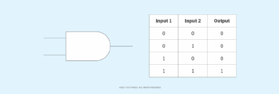
The AND gate produces an output of true solely when each inputs are true. In any other case, the output is fake. In different phrases, the output is 1 solely when each inputs are 1, and 0 if even one of many inputs is 0. The gate is known as so as a result of, if 0 is fake and 1 is true, the gate acts in the identical manner because the logical and operator. Determine 1 offers a fact desk displaying the circuit image and logic combos for an AND gate. Within the image, the enter terminals are on the left, and the output terminal is on the precise.
OR gate
Within the OR gate, which is among the many most generally used logic circuits in digital units and elements, the output is true if one or each inputs are true. If each inputs are false, the output is fake. For the output to be 1, a minimum of one enter have to be 1. The gate will get its identify from behaving just like the logical inclusive or. Determine 2 reveals a fact desk for the OR gate.

XOR gate
The XOR, or unique OR, gate acts in the identical manner because the logical both/or. The output is true if both enter is true, however not each. The output is fake if each inputs are false or each inputs are true. Equally, the output is 1 (true or excessive) if the inputs are completely different, however 0 (false or low) if the inputs are the identical. Determine 3 reveals a fact desk for a 2-input XOR gate.

NOT gate
A logical inverter, generally known as a NOT gate to distinguish it from different forms of digital inverter units, has just one enter. A NOT gate reverses the logic state. If the gate’s enter is 1, then the output is 0. If the enter is 0, the output is 1. One of many solely logic gates that accepts a single enter and produces a single output, the NOT gate can also be one of many easiest since all it does is reverse the enter utilized. As proven in Determine 4, a fact desk for a NOT gate is easy.

NAND gate
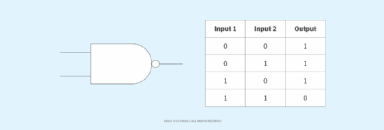
The negated AND, or NAND, gate operates as an AND gate adopted by a NOT gate. Its image is an AND gate with the circle of a NOT gate on the output. The NAND gate produces a false or low output if each inputs are true. In any other case, the output is true. One other solution to visualize it’s {that a} NAND gate inverts the output of an AND gate. It acts within the method of the logical operator and adopted by negation. Determine 5 offers a fact desk displaying the logic of a NAND gate for 2 forms of inputs.
NOR gate
The NOR, or NOT OR, gate is a mix OR gate adopted by an inverter. Its output is true or excessive if each inputs are false or low (logic 0). In any other case, the output is fake. This logic is simple to know with the gate’s fact desk, proven in Determine 6.

XNOR gate
The XNOR, or unique NOR, gate is a mix of an XOR gate adopted by an inverter. Its output is true if the inputs are the identical and false if the inputs are completely different. It produces a real output, no matter whether or not the inputs are true or false. Nonetheless, they have to each be the identical for the output to be true. The XNOR fact desk appears to be like like Determine 7.

Common logic gates
The NAND and NOR gates are referred to as common logic gates since they are often carried out in digital circuits to carry out any Boolean perform with out further logic gates. These gates also can replicate the performance and habits of the opposite gates. In doing so, they assist to simplify the design — and infrequently the fee — of digital ICs.
For instance, two NAND gates can be utilized to create an AND gate. On this case, the primary NAND gate will inverse the logical AND operation of the 2 inputs. The second NAND gate then inverts this output to provide the unique AND logic. Equally, three NAND gates can be utilized to create an OR gate. The primary NAND gate will inverse the primary enter, the second will inverse the output of the primary NAND gate, and the third NAND gate will produce the logical OR of the outputs of the primary two NAND gates.
NAND gates can be used to simulate the outputs of XOR, NOR and XNOR gates. Equally, the NOR logic gate can be utilized to copy the output of all these logic gates:
- AND gate.
- OR gate.
- NAND gate.
- XNOR gate.
- XOR gate.
Composition of logic gates
Excessive or low binary situations are represented by completely different voltage ranges. The logic state of a terminal can, and customarily does, change because the circuit processes information. In most logic gates, the low state is roughly 0 volts, whereas the excessive state is roughly +5 V.
Logic gates will be made from resistors, transistors or diodes. These elements are wired collectively in particular configurations to make sure they remodel the inputs in anticipated methods. Resistors, for instance, can generally be used as a pull-up or pull-down resistor. Pull-up and pull-down resistors are used when there are any unused logic gate inputs to connect with a logic degree 1 or 0. This prevents any false switching of the gate.
Likewise, transistors present switching — turning on or off in response to enter alerts — whereas diodes guarantee present flows in just one course to stabilize the circuit.
Generally used logic gates are transistor-to-transistor logic (TTL) and complementary metal-oxide-semiconductor (CMOS). TTL ICs use negative-positive-negative and positive-negative-positive bipolar junction transistors. CMOS ICs are constructed from metal-oxide-semiconductor or junction field-effect transistors. TTL ICs would possibly generally be labeled because the 7400 collection of chips, whereas CMOS ICs would possibly usually be marked as a 4000 collection of chips.
Study fan-out in digital circuitry, a measure of the utmost variety of digital inputs the output of a single logic gate can feed with out disrupting circuitry operation.
Why are logic gates wanted?
Logic gates carry out primary logical capabilities that each one digital operations depend on, no matter system kind. These capabilities happen at excessive speeds, enabling quick information processing and switch in digital units.
Logic gates are additionally essential for units operating low-power-consumption purposes. It is because the gates eat little energy and require little vitality.
Combining logic gates in varied configurations helps create extra complicated ICs. In principle, there isn’t any restrict to what number of gates will be arrayed collectively in a single system. However in observe, the variety of gates that may be packed right into a given bodily house is restricted. Latest and ongoing developments in computing and electronics engineering are altering this, accommodating ICs and units with extra gates positioned in ever-decreasing areas in more and more complicated units.
The place are logic gates utilized in actual life?
Arrays of logic gates are present in digital ICs. These ICs seem in a large, rising vary of digital units, together with laptops, tablets, smartphones, reminiscence units, digital clocks and televisions. As IC expertise advances, the bodily quantity required for particular person logic gates decreases, and digital units can carry out extra difficult operations sooner.
Quantum computer systems even have their very own model of logic gates, known as quantum logic gates or qutrit quantum gates. These quantum circuits operate utilizing a small variety of qutrits, that are qubits — quantum bits — which have one added dimension. Simply as logic gates are the constructing blocks of digital circuits, qutrit quantum gates are foundational to quantum circuits.
Quantum computing growth can considerably improve information heart operations. Potential purposes of quantum computing embrace optimizing provide chains, bettering monetary modeling, and enhancing AI and machine studying capabilities. Discover future potential quantum computing makes use of.
…………………………………………
Sourcing from TechTarget.com & computerweekly.com
DYNAMIC ONLINE STORE
Subscribe Now


Leave a Reply